News and Announcements

Interested in learning about blacksmithing? Read this!

--News & Announcements--
Upcoming projects:
Building a Frame Saw
Forging a Copper Kettle
Making a pair of leather work boots
Forging and Fletching a Bodkin
Flocking a drawer interior

Monday, April 30, 2018

Wolf's Teeth

The wolf's tooth pattern as seen in northern European ironwork is a combination of strange and fascinating artistic use of material for, as far as I can figure, purely aesthetic reasons. Luke Shearer and I recently took a trip to my good friend Emiliano Carrillo's shop where we took a close look at construction methods and ultimately made an effort at recreating it as closely as possible. The general goal was to try and recreate the similar tooth shape, depth, and spacing as found in historic pieces, mainly referencing the spear found in Lapland (p.151 in Swords of the Viking Age). All of the steel used with exception of a bit of old wrought iron is home made.


The first thought was to use a rack to press into a bar with which to form the teeth. Based on the tooth shape having a slight trapezoidal profile on one side, it seemed like the perfect fit. The above bar is 8 teeth per inch, and in person looks like it would make a nice tight pattern. However, the depth is too shallow and the spacing too tight. For reference of what that looks like in steel, look at the below sax blade that we made as a test piece.


There is a faint strip of wrought between the twists and the edge, and although difficult to see at first it has a slight wiggle. Part of the problem with the rounded bits is that the blade was drawn out a little during forging, and even that deformation was enough to turn the squared corners into a sort of sinusoidal deal. Due to the spacing, another reason that this is not ideal is that the cut depth of the teeth is too shallow to reasonably achieve with a chisel without bending the previous teeth over and closing the gap. That leaves cutting them with a hack saw or modern equivalent, but looking at the originals the continuous grain patterns are mostly suggestive that they were mostly not done that way (not to say that some of them couldn't have been).


The next one we tried was using a 6 tooth per inch rack. The spacing and depth is much closer, but still too tight for the reference spear. I would expect this to work better than the 8 TPI rack because of the extra depth making the weld more resilient to shape changes, but we wound up discarding this due to its size and regularity. Also, the rack forms a sort of positive die where we need a negative one. The wrought almost universally has the flats in its troughs and the edge bar has points in its troughs, the opposite of what would be formed by pressing the rack into the edge billet. While you may be thinking that we could simply press into the wrought instead, I do not think that is how they were made for four main reasons. First, the wrought is incredibly thin (not from grinding) where it joins with the next inward bar, and would not be strong enough to support being used as a die. Second, the wrought itself is fairly soft compared to even a hot edge bar, and the teeth would deform opposite how it appears in the historic patterns. Third, the tooth points are sharp in the wrought, which is very suggestive that the edge bar started with a sharp groove that the wrought filled into, which is reasonably the order it must have been done given the available technology. Last, the grain of the wrought in the teeth is very obviously continuous in most cases, which means the forging of a toothed bar at such regularity would be absurd with the relative ease of instead notching the edge bar... All that is the long way of saying that we abandoned the racks and went to something else.


To get the spacing as accurate as possible, we took a 1:1 scale print of the Lapland spear and measured the tooth spacing. Because of the other indications in the pattern, I found the sections which would have been drawn out the least by subsequent forging and averaged the geometry from the two halves. The final result is a hair under 4 TPI and a depth of 4mm.


On the test bar, all of the teeth were cut based on the tooth previous so any error doesn't compound and gradually increase the size the farther down the bar. Doing this enough, it would not be difficult to maintain an acceptable accuracy doing it freehand, which eliminates the need for dividers.


With the lines scribed, I took a cold chisel and cut just enough for there to be an easy surface to register against. The idea is that these lines are just a guide for a hot chisel.


And finally, cleaning it with a file for the sake of being tidy. Not necessary, and again another thing that would not be needed to do this with a more limited toolchest.

To cut the teeth to their full depth, we made a hot chisel with a taper close to the final shape but a hair steeper to accommodate the distortion from material spreading.


Once we got to cutting the teeth, Emiliano called the hits, Luke struck with a sledge, and I held the chisel. Each heat we cut between 3 and 4 teeth, each to roughly 80% depth. I think this was critical for a few reasons. For one, it made us a lot more aware and had more control over how deep they will be. But it also minimises the deformation of teeth side to side (closing the gaps of the tooth before it) and leaves room for fixing any closure that may have happened during the second pass.


Something that became an issue later on was making sure the edge bar is square and, most importantly, that the top and bottom are parallel. Holding the chisel straight up and down and control of the depth by adjusting the teeth via striker were both fairly easy to correct as we went.


For the first pass, we cut to the aforementioned depth, and without a scribed depth line it was all strictly by eye and in reference to the previous teeth. By the end, we were a bit more confident in the process and one end came out a little better than the other, but all in all remarkably consistent for what it is.


This is the edge bar after the first and second passes. What we did during the second served both to make the depth more uniform as well as ensure that the cut from side to side did not vary. Luke struck more lightly for obvious reasons, which fine tuned how far we able to recut each tooth. Overall, the forward/backward distortion was far less than I expected, and the reopening of any skewed tooth was almost an after effect. Even now the occasional slight rounded tooth is evident, almost exactly like in the Lapland spear.


Because we are using home made steel, there was a little bit of splitting that happened across the grain. It did not prove to be detrimental in any way, and eventually either welded closed or was filled partly with wrought like the teeth.

In order to hold everything together, Emiliano and I held it with tongs on either end while Luke and Eli forged the wrought into the teeth with sledges. The test sax in the first post was done using the press, and worked better because it was so short. By comparison, the length of this one was too much for the distortion that comes from the spreading as it fills the teeth. It can certainly be done in a press, taking care to go slowly and straighten/align everything throughout, but strikers ended up being the most successful.


Having parallel surfaces now is where it really matters most. A slight cant to one side or the other makes the wrought extremely prone to shifting during the forging. To counteract the deformation of the wrought, we tried starting with a wider piece so that there would still be something covering the teeth if it skewed out to one side or the other, but that difference in width also made it more difficult to hold tight to the edge bar. Since the edge is cold and acting as a die, simply tack welding the ends doesn't work.

In order to get the teeth formed, we took the first pass and hammered the entire length so there was always something to register against. In the subsequent heats the forging was more localised and worked from one end to the next. The approximate depth is fairly easily judged by the cooling patterns in the wrought. As a sort of byproduct from the original proportions, the thinness of the wrought above the teeth allows the tops of the edge bar to cool that same pattern into the wrought as it is worked. Similarly, that final thickness of the wrought is almost the same as the overall starting thickness. By having the layer fairly thin (~5.5mm for a 4mm deep tooth), it deforms into the edge bar far easier than it would with a thicker bit of wrought.


Thankfully that wide tooth on the first end we cut on the edge bar served as a solid reference point for realigning the two halves. After forging, there was a bit of flashing left over where the wrought curled down over the edge bar. Based on the previous test pieces, the outside corners are were any weld flaws accumulate, the tiny pockets trapping flux or scale. However, grinding the edges flush significantly reduces this. From what we were able to see, the wrought teeth make first contact in the centre of the edge bar during forming, working outward to the edges. This is extraordinarily convenient because it does not trap anything inside the welds if there is a space for it to escape.

We also found it quite helpful to forge the wrought teeth up, but then during the final pass flip it over so the wrought was on the anvil and use the stability of the edge bar to straighten everything out.


Prior to welding, the bars were soaked briefly in muriatic acid to dissolve scale and then wire wheeled. Cleanup of the teeth with a file does not seem ideal due to the irregularity of the cuts.


Post-weld, the teeth looked fantastic. There were a few slight pockets on the outside of the tooth corners, but only to a depth of half a millimetre or less, and disappeared when we forged it into a blade.


Those few voids near the centre teeth look alarming, but were actually quite shallow. With this edge bar and wrought welded, we took some additional steel and made a few opposing twists and more wrought for the spine.

The meat of the project was home made steel, and in the end we used what would have been the tooth layer as the spine. For the core, there were three layers of opposing twist.


Most of the steel was unconsolidated prior to the project, and the above is a bit of shard steel from Scott Roush's hammer-in several years ago.


The twists were a little precarious and sheared in a few places, but that is part of the uncertainty of using home made steel.


After twisting and squaring, the bars got the same treatment with the wire wheel and were ready for welding. At this size, the bars are more or less the same thickness as the tooth bar, which is to say fairly small. Minimising deformation of the teeth is the main goal, and the few welds that it endures all serve to stretch it out.


All three bars welded up without much trouble, and with another bar of wrought to serve as the spine, the three pieces were ready to be welded for the final pattern.


Above, you can see another hint of teeth in the spine bar. This was the piece we tried to make for the teeth on the edge, but because of the deviation and twisting of the wrought as the teeth pressed into it, it was unable to be used for that. So, because it was already folded hearth steel, we just forged it back on itself to square.


And here is the final welding pass on the blade.


Post weld, everything looked solid. Because of the relative preciousness of material, we forged a stub tang and welded on a piece of wrought.


While forging the last bit of wrought, a quick spark test/trimming the tip showed that there was still a good amount of carbon left in the steel in spite of so many welding/folding/forging cycles.


A little more forging, and this is what the rough billet looked like.


An etch of the cutoff from the tip provides a good look at what the steel is doing inside. It's a little difficult to tell because of the tack welds showing in places, being so near the end. However, the twist bars are all very solidly welded and the weld line of the tooth is very clean.


For the tang, we jump welded the wrought to the body with a single solid blow with a sledge while the other two held it in place.


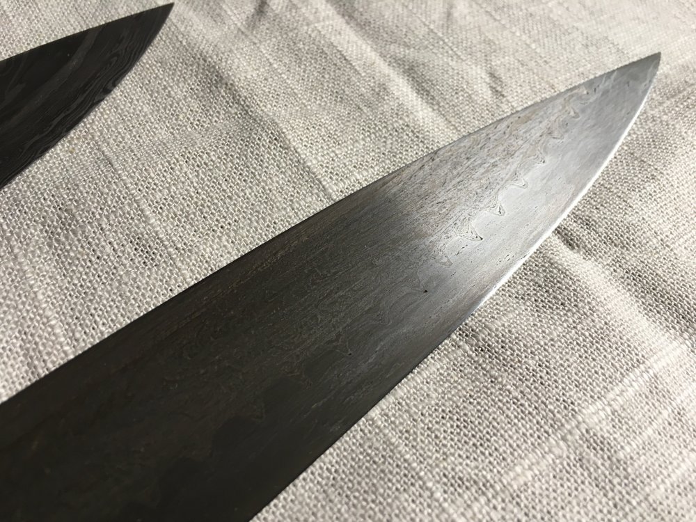
After the final bit of forging, Emiliano did a fantastic job profiling the shape and taper of the point to match the width of the steel. The final tooth geometry is almost spot on with the original, although it did stretch out just a hair. Most striking is perhaps the definition of the grain in both the teeth and the edge bar. The pattern flows beautifully and in a way very suggestive of the originals. I believe this will be a good starting point for further examination, we learned a considerable amount in the process.

Monday, February 26, 2018

Re-Forged


A few years back, I wrote or rambled on the nature of possession and the general state that society has tended towards over the course of the last century. Particularly, towards the materialistic and otherwise disposable mentality which fuels a socioeconomic bio mass with the primeval goal of devouring everything which can be consumed.

Rather than returning to that conversation, I would rather turn towards a more productive (in the literal sense) approach to how life's default to restoration and refurbishment rather than replacement.

Over the last few years as I have become surrounded with the shop, history, and culture of the 1850s and Westward Expansion that is prevalent in the shop wherein I work, a piece of the craft has become steadily more apparent to me. In the past, because the 'abundant material - time deficient' disparity was the controlling factor, I would abandon failed projects at the first sign of trouble and start again with a different approach. While the value of learning the trade under idealised circumstances cannot be overstated, there comes a price in that mistakes become an annoyance rather than a challenge. Now, examining the form of blacksmithing from a more historic and practical standpoint, those frivolous abandonings become less savoury.


Perhaps the driving factor for beginning anew is the pursuit for perfection. If there are flaws, then perfection cannot be attained. If there are failures, then there will be flaws. If failures are not discarded, than there cannot be perfection. But things are not meant to be made perfect. By machines, perhaps. Where tolerances are within the tenth of a thousandth of a micron, perfection suddenly becomes more attainable. When a 1800 degree piece of metal is heated with a pile of coal and smitten with a hammer with tools that are ten times as old as the hands that form it, the metrics for accuracy are suddenly wholly relative and, to a certain extent in the technocratic industrialised world, irrelevant.

When forging the above adze, it began as a body and an edge. Held together with a rivet so I might set the weld in the proper place, the chromium steel had trouble taking to the other half, but in the end it sufficed. Until the edge hot-shorted and crumbled apart. Once, I would have taken it as a sign to either start over with plain carbon steel or else abandon it entirely. But why waste the two days' work? Instead of scrapping the project, I welded a new edge to the lot, adding mass to the body by extending it to a half inch short of the eye. But then the neck became weakened by that transition, so I welded another short piece to span the gap between the eye and the new back plate. At this point, I changed the intention of the design and welded on a square piece to the centre from which I forged the central ridge. Two years ago I would never have thought this was possible, much less probable. By changing how I looked at possibility and shed the trepidation of attempting that which is beyond my former capability, I was able to grow into a better version of myself. In the simplest terms, it is the essence of progress.


They say that necessity is the mother of invention. It may be better said that necessity is the catalyst for growth. Whether as a society or a culture or a trade or as an individual, by seeking the answer to problems rather than restarting them, we are able to find solutions to things which would once be impossible.

When wages were the derivative of tools, care was put into those same tools that they would become worth the their cost. As a result, things were made to be used and to survive their use. When, after the inevitable failure of a hard won life, instead of being retired, where possible they were instead reforged. Restored. Repaired. And part of that cycle is born from the hands who made them. Where every farmer was and every town held a blacksmith, it was in that working knowledge as to fix tools before they were broken. That is to say, the function forced the form. Where there were weaknesses, where there were common failures, where there were susceptibilities and proneness, the maker made better.

In forging a set of timber framing slicks, the two considerations I took above all others both related to the socket. First, an integral socket is something I have been trying to develop on a level of personal skill. By having a socket rather than a tang, the handle is much better suited to the large scale hewing of framed joints. Second, the terminus of the socket. On the first iteration, I tried welding the socket to form an unbroken annulum. With the 5160 steel, the chromium prevented the feasibility of welding something so thin over so long a length. Driven by necessity, I decided to try welding on additional mass in the form of a collar to the top of the socket. This prevents the spring action of an un-welded socket from loosening a handle under heavy use.


Aesthetic flaws are one of the more mundane problems I have come across, as they present no larger issue than pride in craftsmanship. None the less, I feel a certain drive in professionalism to correct what I might once have otherwise left untouched.

Traditionally, the froe, an instrument for splitting logs into wedges or shingles or the general form of a smaller log, is forged by wrapping the eye around a mandrel and welding the seam. Because the blade is fairly thin, it does not make sense to forge it in an integral form to the eye. However, that wrapped eye method often leaves a harsh and unappealing transition between eye and blade.

Taking the path less travelled, I decided to forge a froe from a piece of 2" square tool steel. In doing so, the first step was to slit and drift the eye. When working something so large by hand, there is inevitably some degree of uncertainty in alignment. To counteract the deviation of the chisel as it passes through the steel, I cut from both sides and took the loss in the middle where the asymmetry is easiest forged out. However, lateral alignment is a slightly different problem. There was about a quarter inch offset between the top and bottom holes, leaving a slit in one side which extended half way through the steel. Because it is extremely difficult to correct that once the eye is fully cut, that small gap (yet visible on the heel end where left uncorrected) will either remain in the finished piece or else need to be re-cut all the way through.

For no other reason than to see if I could, I took a small bit of scrap mild steel, forged it into a plug, and welded it into the hole. Using the drift as a press, I drove it in and hammered to create an outward pressure on the plug which set the weld. Subsequent downward pressure forged it mostly flat, leaving behind the relatively smooth transition seen above. As I examine a greater volume of historic work, the more I realise that this sort of fix is not only done but done commonly. Lap welding on new edges to tools, refacing hammers or anvils, fixing cracks with another band of iron welded over the failure, it was as common then as we now use tape or glue.


When those flaws are less aesthetic and more accurately a detriment to structural integrity, I find that the means of salvaging the already-expended-effort is largely the same. Over a year ago, I began forging the body of a carving axe. When slitting the eye, I cut just slightly too close to the back end of the stock and assumed that it would fail while forging the eye. Indeed, it might have been for the size of haft needed for this sort of axe. Then, while sorting through projects to finish, I found it again and took a closer look at what it would take to fix. Indeed, a hundred fifty years ago, this sort of thing would be worth too much to discard.

The thin spot was, fortunately, confined to one side of the eye. As I drifted the eye open, a convenient corner formed that looked as though it would nicely take a spare bit of steel for reinforcement. Without modern welding equipment, the only way to hold onto the bit to be welded was a tricky bit of thinking through the problem and a different pair of tongs. This is, surprisingly, the first (and probably only) time where box jaw tongs worked absolutely perfectly for the job.

In the end, there was only a slight seam left over from the weld due in part to leaving all the scale on both pieces of metal prior to welding. As it were, I learned a valuable lesson in the same school of thought. For blacksmiths are the ultimate manipulators of form, and for all the limitations of working with a hammer and a 3000 degree fire, those same vices become advantages by opening a world of possibility unique to the trade. Through the last eight years since I first struck iron, the constant evolution of thought and conspiratory approach towards problem solving has taught me more than I would have ever imagined, and I suspect that I have only scratched the surface. In all things, not least being the art of forging, I have come to learn that there is always another way through a problem seemingly bereft of solution.

Sunday, January 28, 2018

Archways


Stone archways, as a means of architecture, represent a great many things beyond the confines of masonry. The idea of a keystone is something that more people would recognise in a different context entirely. Rather, most people with whom the words has come up in conversation strangely don't actually know what a keystone is. However, our use of stones to hold open doorways in an otherwise unbroken wall dates back to, at least in bridges, the Sui Dynasty in China in the form of the Anji Bridge constructed over the period of a decade starting in 595 A.D.

My concern with the archway extends a little farther back into the history of builders to the Roman Empire who implemented their learnings of the assimilated Etruscan Empire to build architectural archways that did not rely on piled earth to compensate for the lateral thrust resultant of the radial nature of the stone's arrangement.

While there are literally millennia that span between the first arches and today, I found it difficult enough to locate any mathematical documentation for their design and implementation that I disregarded all of that and started from scratch. Or mostly, anyway.

First off, there are substantially more types of arches than I knew about. Of the ones which I had no aesthetic desire to explore, there are round arches, trefoil arches, three centred arches, elliptical, inflexed, ogee, reverse ogee, tudor, parabolic, etc. etc. Each of these has their own design characteristics which likely corresponds to some far distant cultural revolution and style. Good for them, not so much for me.

Before diving into this, I will say that while drawing these all on onionskin paper was great for transferring lines, it was extraordinarily difficult to photograph for a number of reasons. For that, I will include only a few of the iterations to illustrate what these are all about.


The first and most quickly discarded of the lot were Lancet Arches. These, like the rest of the class that I am dealing with, is designed from two points like foci on an ellipse. Only instead of making a continuous curve, the arcs intersect somewhere and that somewhere is the top of the arch. For the Lancet Arch, the two foci are outside the bounds of the stone, residing somewhere in what will later be the abutment (stones that reside one layer outside the structural arch). To form the intrados and extrados (inner and outer dimensions of the springers) I based these all of of the arbitrary metric of making the arches 5 'units' tall to for the rise and 6 units to the crown.

For the first iteration of the Lancet Arch, I placed the foci at 4 units from the centre, which had a intrados arc radius of 6,4 and the extrados arc radius of 7,2 units. Because the two foci are relatively close together for the length of the arch radius, the sides seemed to come past the vertical tangent and curve back inwards. No good.

To compensate for this, I moved the foci an extra unit farther apart to 5 from centre. This made a more pleasing and more pointy arch, but for a standard doorway dimension of 32" this makes the thing disproportionately tall (an extra 87" on top of an already 80" door). I'll spare you the subsequent iterations of this style of arch but spoiler, they get narrower and pointier.


The Two Centred Drop Arch, or as it is affectionately known the Gothic Pointed Saracenic Arch, is more or less the opposite of the Lancet. Here, the foci are inside the bounds of the arch. In case you were curious, when the foci are on the bounds of the intrads and extrados, it becomes and equilateral arch. Here, however, they are inset and provide a significantly more favourable ratio of rise to span. Because this will be used for a doorway that is more likely than not going to be at least width and a half if not double wide, the lower the rise for a given span the better. A combination of aesthetics and math secretly drove me to optimise this quality throughout the arch exploration that I unwittingly undertook.

Again using the magic constraints of 5 units for the rise and 6 for the crown, the rest is fairly simple. For the Gothic arch, the closer the foci move towards the centre (then becoming a round or semicircular arch), the closer the rise to span ratio moves towards 1. In the above drawing, the top arch has a focal distance of 1 2/3 while the bottom has a focal distance of 1 1/3. You can clearly see how the arch becomes less pointy and closer to a single curved half circle as the distance from the centre decreases.


Ultimately, I liked the look of the arch which had an approximate focal distance of 1,25 units from the centre. but not the constraint of the rise to span ratio it presented. The solution? A Two Centred Pointed Segmental Arch of course! The term Segmental means that the arc length is less than 180 degrees, or is less than a full semicircle. Pointed is a bit obvious, but means that the two Segments meet at some angle that is not parallel tangent. This style combines a few things from various other arch types and, at the expense of introducing considerably more variables than I really wanted to explore, produces wider arches that do not come out round at the crown. While there is nothing wrong with round arches, and with a proud keystone you would probably never notice the difference anyway, the simplicity of that style defeats the purpose of trying to learn more about them.

The Two Centred Pointed Segmental Arch is similar to the Two Centred Drop Arch in that the foci lie within the intrados. However, this is the first one that has them offset from the spring line (where the arch stops and the imposts or skew backs start). Moving the foci above the spring line would give us the same problem that the Lancet Arches have where the shape comes back in and makes it bulbous. Rather than that, the foci drop below the spring line.

Insofar as I am aware, the two most significant variables here are the distance the foci are offset from the centre and how far below the spring line they are. To determine the distance from the centre, I did not just set the spacing at 1 or 1,25 or however many units because there are a few more alignment problems that come from that. So instead, I set a distance of 1 or however many units offset, then drew a series of arcs at a fixed length of 2 units towards the inside of the arch. This formed my sort of anchor point. From the centre of this point I drew another arc, this time at a fixed length of 2,5 units, and intersected it with a circle drawn from the centreline at that original radius of 1 or however many units long. In the top drawing, that radius is 1,25 and in the bottom it is 1 unit. Through a bit of math and a lot of trial and error, I found that doing it this way helps control how much the rise to span ratio changes. Because I did not want a large number for that, the way the foci move by constraining two separate but seemingly unrelated variables keeps it from changing too dramatically while allowing for a fine adjustment of the keystone profile.


Since it is likely none of that made any sense, I'll move on. For the arch I am actually designing (and yes, none of those were actually arches yet), I chose the top one in the previous drawing. It has a rise:span of 1.11:1 and also has a cleaner division of units being that the span is exactly 9 for a crown of 6.

From here, I redrew the intrados and extrados, leaving everything but the foci and spring line out. Because I do not have an accurate and repeatable way of measuring arc lengths, I used the good old guess and check method to divide the arch into a number of equally sized stones. The only difficult part of this is getting the spacing right when the two halves meet at the keystone. I tried a number of divisions, and I found I liked the size best when there are 15 total, 7 on each side plus the keystone. This gives almost square sprigners, but because this is a secondary constraint to the dimensions of the arch itself, it can be changed at any time prior to the stones actually being cut.

From the foci, I took the lines from centre to intersect each of the divisions. Although this is nothing more than an educated guess, like almost everything else so far, the lines must be drawn this way for the stones to actually sit correctly once placed. While there are styles of arch (or pseudo-arches) that do not rely on the transformation of radial force into lateral force via wedges, I can only assume that incorrect geometry here would ultimately lead to failure.


Once all the springers and keystone are drawn, I moved on to the imposts. These are the things the arches sit atop of and support the weight of the stone in the arch. Columns or stacked stone or any number of things can serve as the sides of an archway, but for the sake of completeness I decided to continue with the design experiment.

In order to determine the height of the subsequent imposts and stone beneath, I tried a few things. First, as shown above, using the height of the springer at the intrados. This gives the smallest relative dimension, whereas using the height of a springer at the extrados would give the largest. Using the height of a springer midway between the two is what I ultimately used because it made sense.


And there it is, a finished arch. In later iterations, I will almost certainly change the shape of the keystone as depicted in the bottom half of the previous drawing, but that is a problem for another time. The primary design challenge now is how to integrate the arch into a wall and the adjoining of dissimilar materials. To fill a stone arch with a wooden door, for example, requires fastening one to the other in such a way that it will not be mutually destructive or cause eventual instability.

As I am not an architect, the more I learn about seemingly the simplest of processes, the more I come to appreciate the complexities that secretly reside in untold centuries of our great builders' minds.