Last time I finished the bracing on the back by ripping, planing, and carving thin strips that add much needed strength to the joint and rigidity to its support of the sides. For the top, the process was much the same, although the end result and reason in application is very different. While there is a deal of acoustic design that depends on the shape, number, and position of the braces, I have heard that the instrument gets its tone from the top.

A long while ago I jointed the pieces for the sides and top together, but the back pieces were considerably harder than the tops, so these needed a bit of attention after sitting around for so long. A small bit at the top corner separated outwards, whether from the initial planing or something else, which caused the two edges to misalign. To fix this, I returned the pieces to the bench and paired them together for a light pass with the jointer plane.

To ensure that the two pieces are indeed straight and the edges true to the face of the boards, I turn one of the sides around and clamped them back together. Above you can see that there is about ,25mm difference in height on one end. By having the edges switched around like this, the height disparity will be matched but opposite on the other end, and when the two are perfectly in line again, the edges are straight.
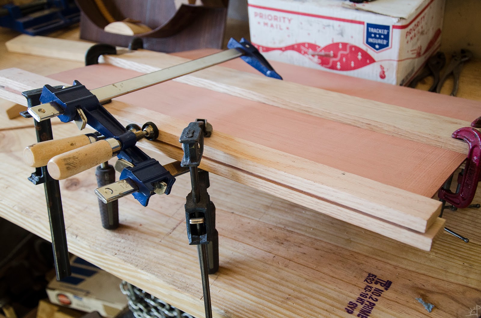
Clamping the long joint together was very difficult, as I do not have any clamps long enough to span the width of the two together. Eventually, I worked it out...

Between the two there was the slightest amount of difference in thickness on one end, which after planing disappeared to leave an invisible seam.

For bringing the surface absolutely smooth, I again used a card scraper, although shortly after this I acquired a scraper plane which I would rather have used. There are a few spots here, although far worse in areas of the neck wood, that make use of an ordinary plane rather difficult. Card scrapers are great, but do not as easily preserve the flatness of the surface as when supported by the sole of a plane.

Having no affiliation with the company, I treat the soles of my planes and surfaces of anything that might rust with Renaissance Wax. I believe I have mentioned it before here somewhere, but it is a micro crystalline wax that was developed for preservation of museum artefacts. On tools, it leaves a very slick finish that reduces friction at an incredible proportion and (as far as I have seen) does not interfere at all with any subsequent finishing. And of course, it helps prevent rust.

With the top assembled, I returned to the final kerfing on the sides. Same as before, I measured bits of the kerfing and matched the angle with the corner blocks.

At this time I also went back for a moment to the inner corner near the heel. I had left the block there a bit oversized and angular, which could use some reduction and shaping. Although not the most significant change, I gradually turned the harsh rectangle into a sort of rounded trapezoid with a block plane. This kept the thickness of the block relatively consistent as it followed the corner.

Serving as a form to hold the shape, the back allowed me to further reinforce the curves and take out a slight bit more of the asymmetric relaxation after steam bending the sides.

A wee bit of the kerfing slipped out of position while the glue dried, which was taken care of with a chisel. Fortunately, the grain direction of the kerfing made this trivial.

Same as before, I scribbled some lines along the entire perimeter of the sides so that I could accurately gage that it was truly flat. This was done in part when I sanded the back, but with the addition of the kerfing, it is important to bring the kerfing perfectly coplanar to the edge of the sides.

Handy spray glue again turned the floor into a sanding block.

A quick test fit shows that the sides are in good shape to align with the top.

Since I used the lot of my cut bracing for the back, I had to make a few new ones. This done shortly after ripping a bow stave out of 4/4 Ipe, and to the saw this spruce felt like cutting air rather than wood. Even still, it was nice to return to the plane for a spell.

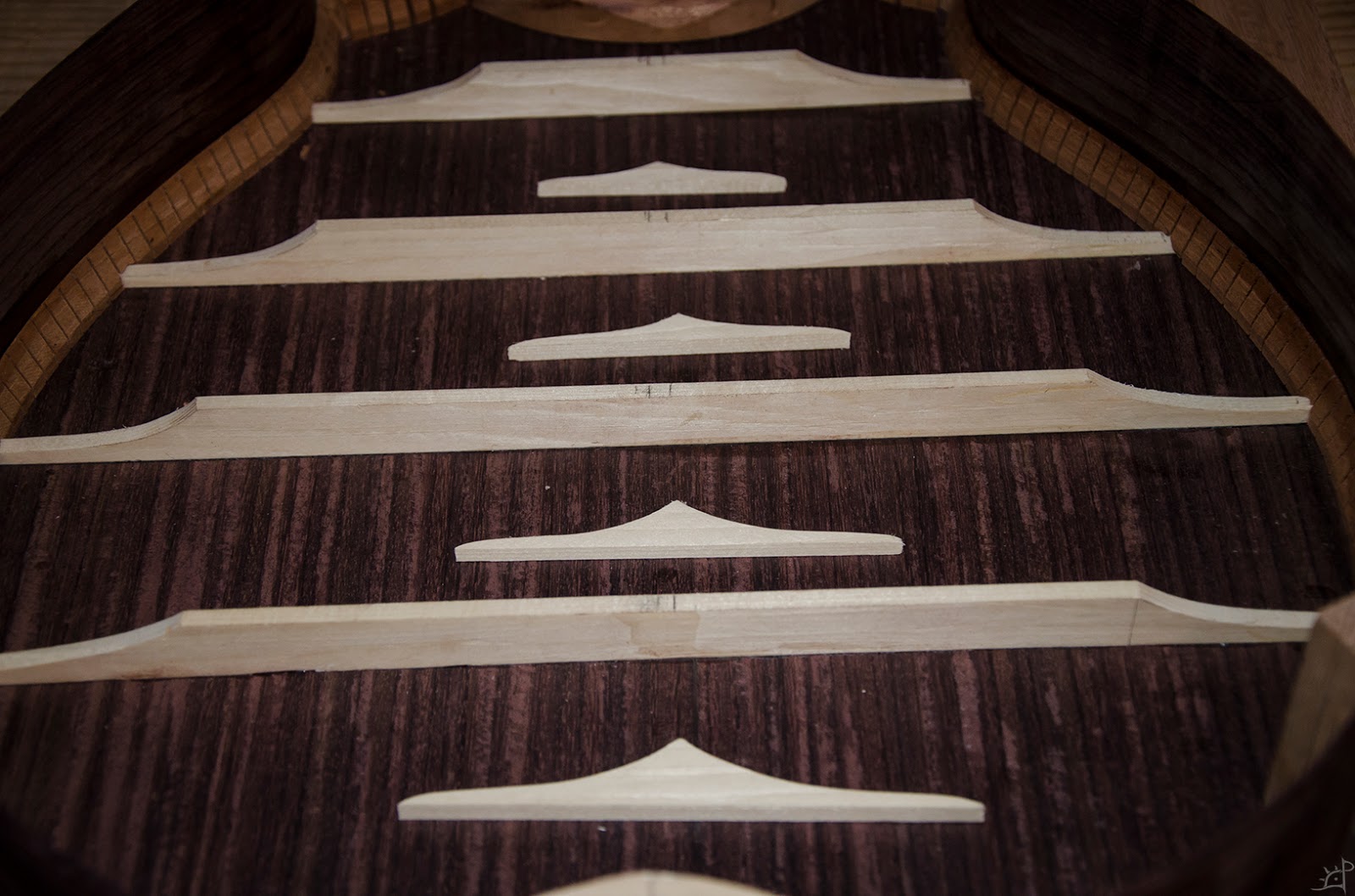
Once thicknessed and cut to length, I brought out the same curve template as used on the back. One side, the one used above, leaves a bit of height left to be accepted by a notch cut into the kerfing. The other blends a brace to the surface of the top without having a hard edge.

As before, I measured the centreline and cut notches at the depth of the ends of the braces. This step marks a point of contention in how acoustic instruments are made. Archtop guitars are, as the name implies, curved on the top. That form is also seen in violins, lutes, mandolins, and everything else that has an acoustic body. Even 'flat top' guitars are not actually flat, but employ a shallow dishing to their tops for added strength and rigidity to withstand the tension of strings. I do not, however, have a dished form in which to brace the top, making it extremely difficult to do evenly and accurately. In spite of having thought of a few crude solutions to this problem, I have chosen to abstain from trying to accomplish this. Instead, I will be making the top truly flat and compensating for string tension in other ways that I will explain when relevant.

Once more, I used two small drops of glue on the braces to temporarily attach them to the top, using clamps as guides for the positioning during pre assembly.

Traced, the braces can be pulled free, the positions perfectly transcribed to their respective places on the top. Those marks from the glue are taken down with a chisel to leave the surface ready for the actual permanent assembly.

Similarly, the two braces are jointed with the shooting board and checked for their straightness with the edge of the plane.

The usual collection of hammers makes its way back out in the form of weights for the glueing. Because there are only two braces here, I did them together to ensure that they did not pitch under the weights, supported by those two other boards perpendicular to them.

And there we have the first two braces. A brief note on their positioning. As I mentioned above, the top braces are where the tone is adjusted. These two here are for rigidity and strength across the joint. On the bottom, I brought it to the apex of that curve in the sides traced above. This one provides, as I see it, the most amount of strength with minimal interference to the other tonal braces. On top, I measured where the sound hole will be cut and adjusted to support the rosette.

In order to position the other tone braces, I found the centre of the top. This was, although very close, NOT the centre of the braces.

In order to preserve space for the rosette, I centred the ebony ring and traced it. Around this, there remainder of the braces will be positioned.

First, I needed more braces, so it was back to ripping down the last remnants of that Englemann Spruce plank. Only after the entirety of this assembly was concluded did I realize that I had another plank for bracing, but of Spanish Cedar. That would have, regrettably, produced warmer and richer tones than this.
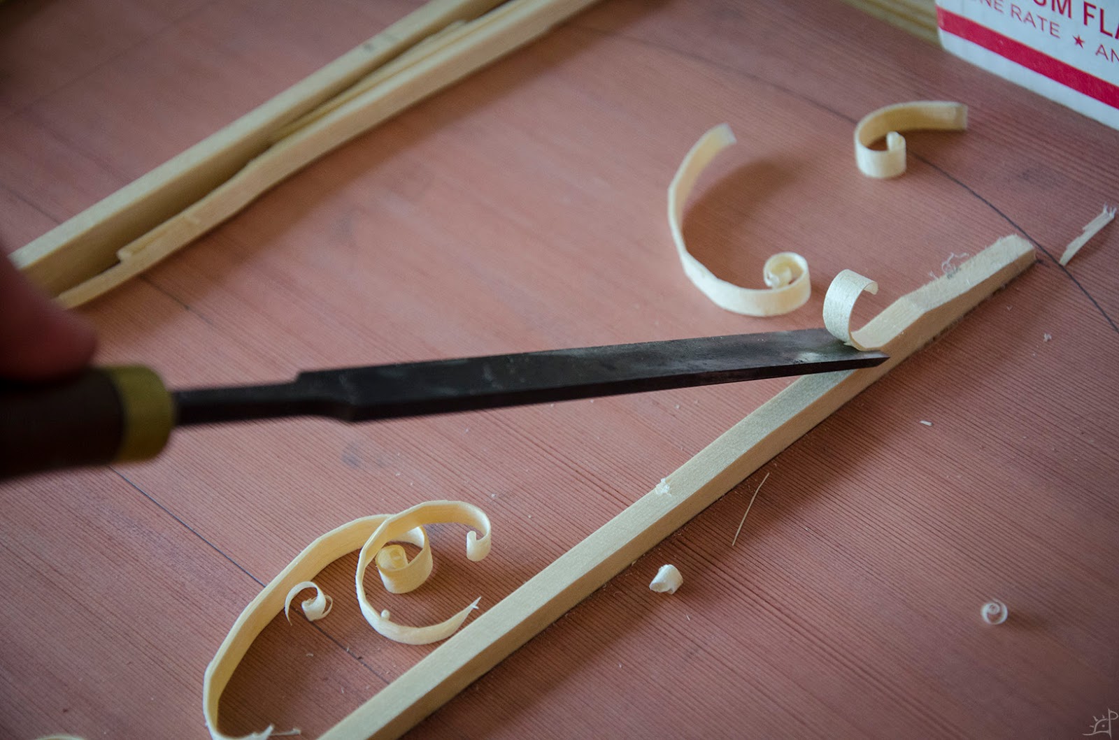
Before approaching the other braces, I decided to use the space available to reduce the height of the existing lower brace and round over some of the corners.

Long, sweeping curves seemed appropriate. Whether or not this has any distinct effect on the acoustics is yet to be determined.

Next up is the cross brace. Notching the two components at equal but opposite angles to meet at the desired position was an interesting challenge that, for the sake of the limited brace wood I had left, worked out alright. That same scalloping template was used for the ends of these, although it was later adjusted with chisels.
Along with the centre notches, I also had to cut slots in the lower brace for the cross to fit. I could alternatively have cut into the cross brace, but the preservation of the flat edge seemed preferable to attempting to cut an angled, round hole in its length in the hope that it fit perfectly the first time.

Test fit, lying flat.

Now, reducing the excessive amount of material in the cross brace took a bit of drawing and redrawing until I found a curve that looked satisfactory. On the shorter end, there were shorter curves, on the longer end, longer curves.

Based on nothing more than a guess and some visual inspection of classic bracing forms, I devised the pattern I used. It might be great, could quite possibly be awful, but will certainly add strength to the otherwise fragile top.

Looking rather skeletal, the cross brace is fitted, so I turned my attention to the radial braces.

Playing off of a fanlike symmetry, I cut and placed two braces to fit between the bottom brace and upper limb of the cross brace.

And then repeated the pattern on the other side. Another brace will eventually be fitted on the top quadrant of the cross brace just below the sound hole, but I will wait until the hole is actually cut and the rosette inlaid before determining where is appropriate.

The classic upended bag of hammers technique holds the braces firmly down while the glue dries. As bad as it looks, there is a decently even distribution of weight on each of the members and along their entire length.

Finally, a third radial brace is added to the bottom side. This is to compensate for the asymmetry in the sides, there being that swept corner that you can faintly see the tracing of in the bottom right of the above picture.

Once the angle was set, I marked the length by tracing over the angle near the back brace and the meeting with the sides on the other.

With that cut, I was able to notch out a slot in the cross brace for it to slide into. A bit of carving to bring the scalloped end smoothly into the back brace, and it began to look like it belonged.

Concurrently, I also began to shave down the corners on all the braces. This is, as best I understand, something that can also be done before they are attached, but even that slight introduction of stress on the wood can bend it into curves and shapes that I want nothing to do with.

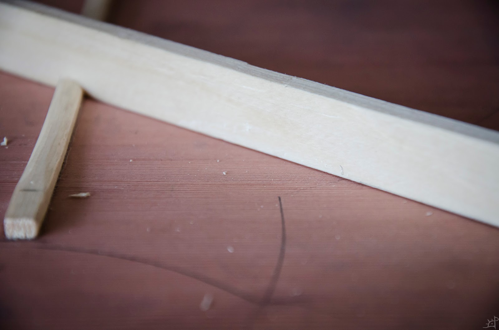
A slight bit of sanding smooths everything out.

All nice and sanded, smooth as can be.

Now that all the pieces are fixed in place, I was able to fit the sides down atop it and mark where the radial braces needed to be trimmed. They could have been notched into the kerfing like the rest, but there was no real need and this was far easier.

And there sits the internal skeleton of the top.
Next up will be figuring how to construct and attach the neck to the body.